Iranian Classification Society Rules

< Previous | Contents | Next >
Section 5 Castings
501. Steel castings
1. Application
(1) The requirements in 501. are to apply to the steel castings intended to be used for the compo- nents specified in the relevant Parts of hull construction equipments and machinery, except that defined in 502., 503. and 504.
(2) Steel castings having characteristics differing from those specified the requirements in 101. 2.
2. Kinds
The steel castings are classified as specified in Table 2.1.68.
in 501. are to comply with
![]()
![]()
![]()
![]()
![]()
Table 2.1.68 Grades and Mechanical Properties
Kind | Grade | Yield strength (N mm ) | Tensile strength (N mm ) | Elongation (%) ( ) | Reduction of area (%) |
Carbon steel castings | RSC 410 | 205 min. | 410 min. | 24 min. | 38 min. |
RSC 450 | 225 min. | 450 min. | 22 min. | 29 min. | |
RSC 480 | 245 min. | 480 min. | 20 min. | 27 min. | |
RSC 520 | 265 min. | 520 min. | 18 min. | 25 min. | |
RSC 560 | 305 min. | 560 min. | 15 min. | 20 min. | |
RSC 600 | 325 min. | 600 min. | 13 min. | 20 min. | |
Low alloy steel castings | RSC 440A | 245 min. | 440 min. | 22 min. | 40 min. |
RSC 480A | 275 min. | 480 min. | 17 min. | 35 min. | |
RSC 550A | 345 min. | 550 min. | 16 min. | 35 min. | |
NOTES: 1. For intermediate values of the tensile strength, the minimum values for yield strength, elongation and reduction of area may be obtained by interpolation and the value at the first decimal place is to be subjected to the method of counting fractions over 1/2 as one and disregarding the rest. 2. The upper limit of the tensile strength is to be within 150 N mm from minimum tensile strength of each grade. | |||||
![]()
![]()
3. Manufacture
(1) All flame cutting, scarfing or arc-air gouging to remove the risers and surplus metal is to be undertaken in accordance with recognized good practice and is to be carried out before the final heat treatment. Preheating is to be employed when necessitated by the chemical composition or thickness of the castings. If necessary, the affected areas are to be either machined or ground smooth.
(2) Where the surface of steel castings is hardened by induction hardening, nitriding, cold rolling or other methods, the proposed methods of manufacture are to be approved by the Society.
(3) When two or more castings are joined by welding to form a composite component, the pro-
posed welding procedure is to be submitted for approval to the Society. If necessary, welding procedure qualification tests may be required.
![]()
![]()
4. Chemical composition See Guidance
(1) All castings are to be made from killed steel and the chemical composition is to comply with the overall limits given in Table 2.1.69.
(2) The chemical composition of each heat is to be determined by the
taken preferably during the pouring of the heat. When multiple heats
![]()
ladle, the ladle analysis shall apply.
manufacturer on a sample
are tapped into a common
![]()
Table 2.1.69 Chemical Composition (%)
Steel Type | Application | Chemical composition (%) | ||||||||||
C | Si | Mn | S | P | Residual elements | Total residuals | ||||||
Cu | Cr | Ni | Mo | W | ||||||||
Carbon steel casting | Casting for non-welded construction | 0.40 max. | 0.60 max. | 0.50- 1.60 | 0.040 max. | 0.040 max. | 0.30 max. | 0.30 max. | 0.40 max. | 0.15 max. | - | 0.80 max. |
Casting for welded construction | 0.23 max.(1) | 0.60 max. | 1.60 max. | 0.040 max. | 0.040 max. | 0.30 max. | 0.30 max. | 0.40 max. | 0.15 max. | - | 0.80 max. | |
Low alloy steel casting | 0.25 max. | 0.60 max. | 1.50 - 0.80 | 0.030 max. | 0.030 max. | 0.50 max. | 1.50 max. | 0.50 max. | 1.20 max. | 0.10 max. | 1.00 max. | |
NOTES : (1) The carbon content may be, subject to approval by the Society, increased above this level provided that the carbon equivalent (Ceq) is not more than 0.41 %. See Guidance | ||||||||||||
![]()
![]()
(3) Unless otherwise required suitable the discretion of the manufacturer. analysis.
5. Heat treatment
grain refining elements such as aluminium may be used at The content of such elements is to be reported in the ladle
![]()
(1) Steel castings are to be annealed, normalized, normalized and tempered, or quenched and tempered. No annealed casting is to be removed from the furnace until the temperature of the entire furnace charge has fallen to or below a temperature of 455°C. The tempering temperature is to be not less than 550 .
(2) Steel castings which are locally heated or subjected to any cold work after heat treatment, are
to be stress-relieved.
![]()
(3) Castings for components such as crankshafts and engine bedplates, where dimensional stability and freedom from internal stresses are important, are to be given a stress relief heat treatment.
![]()
This is to be carried out at a temperature of not less than 550 followed by furnace cooling to 300 or lower.
(4) Heat treatment is to be carried out in properly constructed furnaces which are efficiently main-
tained and have adequate means for control and recording of temperature. The furnace di-
mensions are to be such as to allow the whole casting to be uniformly heated to the necessary temperature In the case of very large castings alternative methods for heat treatment will be specially considered by the Society.
Sufficient thermocouples are to be connected to the furnace charge to measure and record that its temperature is adequately uniform unless the temperature uniformity of the furnace is verified at regular intervals.
(5) The foundry is to maintain records of heat treatment identifying the furnace used, furnace charge, date, temperature and time at temperature. The records are to be presented to the Surveyor on request.
6. Mechanical properties
(1) The mechanical properties of the steel castings are to comply with the requirements given in
Table 2.1.68.
![]()
![]()
(2) Impact tests should be required on carbon steel castings intended for welded construction such as cast sternframes, rudder horns and shoepieces. The results of impact test is to be in accord- ance with the Guidance relating to the Rules specified by the Society. See Guidance
7. Selection of test specimens
(1) At least one test sample is to be provided for each casting. Unless otherwise agreed these test samples are to be either integrally cast or gated to the castings and are to have a thickness of not less than 30 mm. Test material, sufficient for the required tests and for possible retest pur- poses is to be provided for each casting or batch of castings. One tensile test specimen is to be taken from each test sample.
![]()
(2) The test samples are to be heat treated together with the castings which they represent and are not to be detached from the casting until the specified heat treatment has been completed and they have been properly identified.
(3) For castings where the method of manufacture has been specially approved by the Society in
accordance with 3 (2), the number and position of test samples is to be agreed Society having regard to the method of manufacture employed.
(4) Number of test specimens is to comply with the requirements of Table 2.1.70.
with the
Table 2.1.70 Number of Test Specimens
Condition of casting | Number of test specimens |
Where the weight of one steel casting is between 1 ton and 10 tons inclusive | 1 for each casting(1) |
Where the casting is of complex design or where the finished weight exceeds 10 tons | 2 for each casting(1) |
Where large castings are made from two or more casts which are not mixed in a ladle prior to pouring. | Two or more corresponding to the number of casts involved(1) |
Where a number of small castings with a weight of 1 ton or less which are to be of similar type and dimensions, made from one cast and heat-treated in the same furnace charge. | 1 for each batch of castings(2) |
NOTES: (1) These test samples are to be integrally cast at locations as widely separated as possible. (2) Test sample are to be separately casted and are to have suitable dimensions. | |
![]()
![]()
8. Surface and dimension inspections See Guidance
(1) When heat treatment and machining are finished and, if necessary, at a proper time during ma- chining, surface inspection is to be carried out. Where applicable, this is to include the exami- nation of internal surfaces. Testing methods and acceptance criteria are to be in accordance with the Guidance relating to the Rules specified by the Society.
(2) All castings are to be cleaned and adequately prepared for examination; suitable methods include pickling, caustic cleaning, wire brushing, local grinding, shot or sand blasting. The surfaces are
not to be hammered, peened or treated in any way which may obscure defects.
(3) The dimension inspection of the steel castings is to be conducted under the responsibility of the
manufacturer, unless otherwise specified.
9. Quality
(1) All castings are to be free from surface or internal defects, which would be prejudicial to their proper application in service.
(2) In the event of any casting proving to be defective during subsequent machining or testing it is
to be rejected notwithstanding any previous certification.
10. Non-destructive inspection
(1) The steel castings intended for stern frame, rudder post and other important structural members or the steel castings specified in Pt 5, Ch 2, 201. 1 are to be subjected to ultrasonic tests at an appropriate stage of the manufacturing process and the test reports are to be showed or sub- mitted to the Surveyor. Testing methods and acceptance criteria are to be in accordance with the Guidance relating to the Rules specified by the Society.
![]()
![]()
(2) The important parts of the following steel castings are to be subjected to magnetic particle tests at an appropriate stage of the manufacturing process. But, machining surfaces may be subjected to liquid penetrant tests. Testing methods and acceptance criteria are to be in accordance with the Guidance relating to the Rules specified by the Society. See Guidance
(a)
(b)
(c)
(d)
Steel castings intended for stern frame, rudder post and other important structural members. Steel castings specified in Pt 5, Ch 2, 201. 1.
![]()
Propellers. Turbine castings.
![]()
(3) When required by the relevant construction Rules, castings are to be pressure tested before final acceptance. These tests are to be carried out in the presence of the Surveyor and are to be to their satisfaction.
(4) In place of the test methods specified in (1) and (2), the Society may accept the application of other non-destructive inspections considered adequate by the Society.
(5) The Society may require non-destructive inspections by radiographic test, ultrasonic test, mag-
netic particle test or penetrant test not only for the steel casting specified in (1) and (2) but al- so for the steel casting deemed necessary by the Society.
(6) The welding parts of steel castings used to welded construction are to be subjected to non-de- structive inspections considered adequate by the Society.
11. Repair of defects
(1) General
(i) The approval of the Society is to be obtained where steel castings from which defects were
removed are to be used with or without weld repair.
![]()
![]()
(ii) Procedure of removal of defect and weld repair is to be in accordance with the Guidance relating to the Rules specified by the Society. See Guidance
(iii) Where the defective area is to be repaired by welding, the excavations are to be suitably shaped to allow good access for welding. The resulting grooves are to be subsequently
ground smooth and complete elimination of the defective material is to be verified by mag-
netic particle test or liquid penetrant test.
(iv) Shallow grooves or depressions resulting from the removal of defects may be accepted pro- vided that they will cause no appreciable reduction in the strength of the casting. The re-
sulting grooves or depressions are to be subsequently ground smooth and complete elimi- nation of the defective material is to be verified by magnetic particle test or liquid penetrant
test.
(v) The manufacturer is to maintain full records detailing the extent and location of repairs made to each casting and details of weld procedures and heat treatments applied for repairs. These records are to be available to the Surveyor and copies provided on request.
(2) Weld repairs
When a casting can be repaired by welding, the following requirements apply:
(i) Before welding is started, full details of the extent and location of the repair, the proposed
welding procedure, heat treatement and subsequent inspection procedures are to be submitted for approval.
(ii) All castings in low alloy steels and all castings for crankshafts are to be suitably pre-heated
prior to welding. Castings in carbon steel may also require to be pre-heated depending on their chemical composition, the dimensions and position of the weld repairs.
(iii) Welding is to be done under cover in positions free from draughts and adverse weather
conditions by qualified welders with adequate supervision. As far as possible, all welding is to be carried out in the downhand (flat) position.
(iv) The welding consumables used are to be of an appropriate composition, giving a weld de-
posit with mechanical properties similar and castings.
Welding procedure tests are to be carried out
isfactory mechanical properties can be obtained
![]()
(v) After welding has been completed the castings
in no way inferior to those of the parent
by the manufacturer to demonstrate that sat- after heat treatment as detailed in 5.
are to be given either a suitable heat treat-
ment aint aactceomrdpaenrcaeturwe itohf tnhoet rleeqssuirtehmanen5ts50of .prTehveioutysp5e o(1f) hoerat atrsetartemssenrteleiemvpinlogyehdeawt itlrleabte-
dependent on the chemical composition of the casting and the dimensions, positions and na- ture of the repairs .
(vi) Subject to the prior agreement of the Society, special consideration may be given to the
omission of postweld heat treatment or to the acceptance of local stress-relieving heat treat- ment where the repaired area is small and machining of the casting has reached an ad-
vanced stage.
(vii) On completion of heat treatment the weld repairs and adjacent material are to be ground smooth and examined by magnetic particle or liquid penetrant testing. Supplementary exami-
nation by ultrasonics or radiography may also be required depending on the dimensions and
nature of the
non-destructive
original defect. Satisfactory results are to be obtained from all forms of
testing used.
![]()
12. Retest procedure
(1) Where the tensile test fails to meet the requirements, additional test may be carried out in ac- cordance with the requirements of 109.
(2) The additional tests are to be taken, preferably from the same, but alternatively from another,
test sample representative of the casting or batch of castings.
(3) At the option of the manufacturer, when a casting or batch of castings has failed to meet the test requirements, it may be reheat treated and re-submitted for acceptance tests.
13. Marking
(1) The grade of material all steel castings. In than 250 kg in mass.
and the manufacturer"s name or trade mark are to be cast or stamped on addition, the cast number is to be stamped on all steel castings not less The Society's brand indicating satisfactory compliance with the require-
ments is to be stamped in the vicinity of the foregoing marks.
(2) For steel castings to which the requirements given in note 1 of the Table 2.1.68, the material symbols are specified as R SC - (or R SC - A ) and the required tensile strength is to be filled in symbol " - ". (e.g. For carbon steel castings which the required tensile strength is 420 N /mm2, R SC 420)
(3) Where carbon steel castings are intended for welded hull construction specified in Table 2.1.69, "W" is to be suffixed to the marking. (e.g, R SC 420-W )
14. Additional requirements for crank throw
(1) In case where semi-built-up crank throw for diesel engines is made of steel casting, the manu- facturing procedure is to be approved by the Society.
(2) Where special manufacturing methods are adopted to reduce the size of crank throw according
to the requirements in Pt 5, Ch 2, 208, the preliminary test instructed by the Society are to be carried out.
502. Steel castings for chains
1. Application
(1) These requirements are to apply to the steel castings used for anchor chain cables and accesso- ries specified in Pt 4, Ch 8 (hereinafter referred to as "steel castings").
![]()
![]()
(2) Steel castings for manufacture of offshore mooring chain accessories are to be in accordance with the Guidance relating to the Rules specified by the Society. See Guidance
(3) Steel castings having characteristics differing from those specified in 502. are to comply with
the requirements in 101. 2.
2. Kinds
The steel castings are classified as specified in Table 2.1.71
Table 2.1.71 Grade of Steel Casting
Grade | Application |
RSCC 50 | Grade 2 chain |
RSCC 70 | Grade 3 chain |
3. Heat treatment
(1) Steel castings are to be normalized, normalized and tempered, quenched and tempered or heat treated by the process approved by the Society.
(2) Steel castings which are locally heated or subjected to any cold work after heat treatment, are to be stress-relieved by the approved methods.
(3) Flame cutting or scarfing to remove risers and surplus metals is to be completed before final
heat treatment of the steel castings.
4. Chemical composition
![]()
Chemical composition of steel castings is to be subjected to the special approval by the Society.
![]()
5. Mechanical properties
The mechanical properties of steel castings are to comply with the requirements given in Table 2.1.72.
![]()
![]()
![]()
![]()
![]()
![]()
Table 2.1.72 Mechanical Properties
Grade | Tensile test | Impact test(1) | ||||
Yield strength (N m m ) (2) | Tensile strength (N m m ) (2) | Elongation (%) ( ) | Reduction of area (%) | teTesting ) mp. ( | Average absorbed energy (J) | |
RSCC 50 | 295 min. | 490~690 | 22 min. | - | - | - |
RSCC 70 | 410 min. | 690 min. | 17 min. | 40 min. | 0 | 60 min. |
NOTE: (1) When the absorbed energy of two or more test specimens among a set of test specimens is less in value than the specified average absorbed energy or when the absorbed energy of a single test speci- men is less in value than 70 % of the specified average absorbed energy, the test is considered to have failed. | ||||||
6. Selection of test specimens
(1) One test sample is to be taken from castings of similar dimensions originating from the same heat treatment charge and the same cast of steel. In this case, the test sample may be the test assembly cast with the body of casting and similar area. The tensile and impact test specimens are to be taken from the test sample in the longitudinal direction at a depth of 1/6 diameter from the surface specified in Fig 2.1.5.
(2) For R SC C 50, one tensile test specimen, and for other grades of chain castings, one tensile test specimen and one set (3 pieces) of impact test specimens are to be taken from the test sample.
7. Surface inspection
Steel castings are to be subjected to the surface inspection after completion of the final heat treatment.
8. Quality
Steel castings are to be of uniform quality and free from harmful defects.
9. Non-destructive inspection
A suitable non-destructive inspection, such as an ultrasonic test, may be required where deemed necessary by the Society.
10. Repair of defects
The repair of defects for steel castings is generally to be carried out in accordance with the re- quirements in 501. 11.
11. Retest procedure
Where the tensile test or impact test on the selected first test specimens fails to meet the require- ments, additional tests may be conducted according to the requirements given in 306. 7.
12. Marking
Steel castings which have satisfactorily complied with the required tests are to be marked with the identification mark in accordance with the requirements in 501. 13 (1).
![]()
503. Stainless steel castings
1. Application
(1) Tinhge sryesqtuemiresmuesnetds
![]()
ate lotow atpepmlypetroatutrhee (s-t1a6in5less asntdeelovcearstiinngsdefsoirgnvatlevmespearantdurep)ipeserfvititcinegsorincoprripo-
sion-resisting service (hereinafter referred to as "steel castings").
(2) Steel castings having characteristics differing from those specified in 503. are to comply with
the requirements in 101. 2.
Kinds 2.
The steel castings are classified as specified in Table 2.1.73.
Heat treatment 3.
Steel castings are generally to receive a solid solution treatment.
Chemical composition 4.
The chemical composition of steel castings is
2.1.73.
to comply with the requirements given in Table
Table 2.1.73 Grades and Chemical Composition
Grade | Chemical composition (%) | ||||||||
C | Si | M n | P | S | N i | C r | M o | O ther | |
R SSC 13 | 0.08 max. | 2.00 max. | 2.00 max. | 0.040 max. | 0.030 max. | 8.00~11.00 | 18.00~21.00 |
|
|
R SSC 14 | 1.50 max. | 10.00~14.00 | 17.00~22.00 | 2.00~3.00 |
| ||||
R SSC 16 | 0.030 max. | 12.00~16.00 |
| ||||||
R SSC 17 | 0.08 max. | 2.00 max. | 12.00~15.00 | 22.00~26.0 | |||||
R SSC 18 | 19.00~22.00 | 23.00~27.0 | |||||||
R SSC 19 | 0.030 max. | 8.00~12.00 | 17.00~21.0 |
|
| ||||
R SSC 21 | 0.08 max. | 9.00~12.00 | 18.00~21.0 | 1.35 Nb+Ta 10×C | |||||
![]()
![]()
![]()
![]()
5. Mechanical properties
(1) The mechanical properties of steel castings are
2.1.74.
to comply with the requirements give in Table
(2) Where deemed necessary by the Society, impact test or corrosion-resistance test may be required in addition to the specified tests.
6. Selection of test specimens
(1) Where a stainless steel casting is 500 kg and over in weight, one tensile test specimen and one hardness test specimen are to be taken from each casting.
(2) Where a number of stainless steel castings of similar form and size, each of which weight less than 500 kg, are cast from the same charge, two tensile test specimens and two hardness test specimens are to be taken from each group of castings simultaneously heat treated in the same
furnace.
(3) Hardness test specimen may be a portion of tensile test specimen.
7. Marking
Steel castings which have satisfactorily complied with the required tests are to be marked with the identification mark in accordance with the requirements in 110.
![]()
![]()
![]()
![]()
![]()
![]()
Table 2.1.74 Mechanical Properties
Grade | Tensile test | Hardness test | ||
Yield strength (N mm ) | Tensile strength (N m m ) | Elongation( ) ( ) | Brinell H B | |
RSSC 13 | 185 min. | 440 min. | 26 min. | 183 max. |
RSSC 14 | ||||
RSSC 16 | 175 min. | 390 min. | 31 min. | |
RSSC 17 | 205 min. | 440 min. | 26 min. | |
RSSC 18 | 185 min. | |||
RSSC 19 | 390 min. | 31 min. | ||
RSSC 21 | 205 min. | 440 min. | 26 min. | |
504. Steel castings for low temperature service
1. Application
(1) Ttehmes reinqtueinredmedenttos abree utosedappatly thtoe
![]()
tdheesigsnteetlemcapsetrinatgusrefolrowvearlvethsanand0 pipien filtitqinugefsieidn gpaispincgarrsiyesrs-
(hereinafter referred to as "steel castings").
(2) Steel castings other than specified in 504. or those used in other parts to comply with the requirements given in 101. 2.
2. Kinds
The steel castings are classified as given in Table 2.1.75.
than specified in (1) are
Table 2.1.75 Grades and Chemical Composition
Grade | Deoxidation | Chemical composition (%) | ||||||
C | Si | M n | P | S | N i | M o | ||
RLCA | Fully killed fine grain | 0.30 max. | 0.60 max. | 1.00 max. | 0.035 max. | 0.035 max. | - | - |
RLCB | 0.25 max. | 0.50~0.80 | 0.45~0.65 | |||||
RLC 2 | 0.25 max. | 0.030 max. | 0.030 max. | 2.00~3.00 | - | |||
RLC 3 | 0.15 max. | 3.00~4.00 | ||||||
3. Heat treatment
Steel castings are to be normalized or normalized and tempered.
4. Deoxidation practice and chemical composition
The deoxidation practice and chemical composition of steel castings ments given in Table 2.1.75.
5. Mechanical properties
are to comply with the require-
(1) The mechanical properties of
2.1.76.
(2) Where deemed necessary by specified in (1).
steel castings are to comply with the requirements given in Table
the Society, other tests may be required in addition to the tests
![]()
![]()
![]()
![]()
![]()
![]()
![]()
Table 2.1.76 Mechanical Properties
Grade | Tensile test | Impact test (2) | |||||
Yield strength (N mm ) | Tensile strength (N mm ) | Elongation (%) ( ) | Reduction of area (%) | Test temp. ( ) | Average absorbed energy (J) | ||
RLC A | 245 min. | 450 min. | 21 min. | 35 min. | -40(1) | 27 min. | |
RLC B | -50(1) | ||||||
RLC 2 | 275 min. | -70 | 34 min. | ||||
RLC 3 | -95 | ||||||
NOTES: (1) Impact test temperature for castings specified in Pt 7, Ch 5 is to be 5 below the design temperature or -20 , whichever is the lower. (2) When the absorbed energy of two or more test specimens among a set of test specimens is less in val- ue than the specified average absorbed energy or when the absorbed energy of a single test specimen is less in value than 70 % of the specified average absorbed energy, the test is considered to have failed. | |||||||
![]()
![]()
6. Selection of test specimens
(1) Where a steel casting is 500 kg and three impact test specimens are to be
(2) Where a number of steel castings of
over in weight, one tensile test specimen and one set of taken from each casting.
similar form and size, each of which less than 500 kg in
weight, are cast from the same charge, two tensile test specimens and two sets of six impact
test specimens are to be taken from each group of castings simultaneously heat treated in the
same furnace.
7. Retest procedures
(1) Where the tensile tests fail to meet the requirements, additional tests may be carried out accord- ing to the requirements given in 109.
(2) Regarding the impact tests, additional tests are to be carried out according to the requirements
given in 304. 9 (2).
8. Marking
Steel castings which have satisfactorily complied with the required tests are to be marked with the identification mark in accordance with the requirements in 501. 13 (1) and in case the requirement in Note (1) of Table 2.1.76 has been applied, "impact test temperature T" is to be suffixed to the marking. (e.g. RL CA - 25T)
505. Stainless steel casting for propeller
1. Application
![]()
![]()
(1) These requirements are applicable to the manufacture of stainless steel casting(hereinafter referred to as "steel propeller casting") for propellers, blades and bosses. These requirements may al- so be used for the repair of propellers damaged in service, subject to prior agreement with the Society. See Guidance
(2) Steel propeller castings having characteristics differing from those specified in ply with the requirements in 101. 2.
2. Kinds
Steel propeller castings are classified as specified in Table 2.1.77.
3. Chemical composition
![]()
Chemical composition is classified as specified in Table 2.1.77.
505. are to com-
![]()
Table 2.1.77 Kinds and Chemical Composition
Alloy type | Chemical composition (%) | |||||
C | M n | C r | M o(1) | N i | ||
12Cr 1N i | Martensitic | 0.15 Max. | 2.0 Max. | 11.5 - 17.0 | 0.5 Max. | 2.0 Max. |
13Cr 4N i | 0.06 Max. | 2.0 Max. | 11.5 - 17.0 | 1.0 Max. | 3.5 - 5.0 | |
16Cr 5N i | 0.06 Max. | 2.0 Max. | 15.0 - 17.5 | 1.5 Max. | 3.5 - 6.0 | |
19C r 11Ni | Austenitic | 0.12 Max. | 1.6 Max. | 16.0 - 21.0 | 4.0 Max. | 8.0 - 13.0 |
NOTE : (1) Minimum values may be in accordance with recognised national or international standards, subject to pri- or agreement with the Society. | ||||||
4. Heat treatment
Martensitic castings are to be austenitized(quenching) and tempered. Austenitic castings should be solution treated.
5. Mechanical properties
(1) The mechanical properties are to meet the requirements in Table 2.1.78 These values refer to
the test specimens machined from integrally cast test bars attached to the hub or
Types | Tensile test | Impact test | |||
Yield strength (1) (N mm ) | Tensile strength (N m m ) | Elongation (%) | Reduction area (%) | Average absorbed energy (J) (3) | |
12Cr 1Ni | 440 Min. | 590 Min. | 15 Min. | 30 Min. | 20 Min. |
13Cr 4Ni | 550 Min. | 750 Min. | 15 Min. | 35 Min. | 30 Min. |
16Cr 5Ni | 540 Min. | 760 Min. | 15 Min. | 35 Min. | 30 Min. |
19Cr 11Ni | 180 Min.(2) | 440 Min. | 30 Min. | 40 Min. | - |
NOTES (1) 0.2 % yield strength (2) 1.0 % yield strength is min. 205 N m m . (3) Not required for general service and the lowest Ice class notation(Grade ID). For other Ice class no- tations, tests are to be made -10 . | |||||
Table 2.1.78 Mechanical Properties
![]()
![]()
![]()
![]()
![]()
![]()
6. Selection of test samples and specimens
(1) Where possible, the test samples attached on blades are to be located in an area
0.6 R , where R is the radius of the propeller.
on the blade.
between 0.5 to
(2) The test samples are not to be detached from the casting until the final heat treatment has been carried out. Removal is to be by non-thermal procedures.
(3) Separately cast test samples may be used subject to prior approval of the Society. The test sam- ples are to be cast from the same heat as the castings represented and heat treated with the castings represented.
(4) At least one set of mechanical tests is to be made on material representing each casting.
However, where a number of small propellers of about the same size, and less than 1 m in di- ameter, are made from one cast and heat treated in the same furnace charge, a batch testing procedure may be adopted using separately cast test samples of suitable dimensions. At least
one set of mechanical tests is to be provided for each multiple of five castings in the batch.
![]()
7. Surface and dimension inspection
(1) Steel propeller castings are to be subjected to the surface inspection by the Society at the final process and other proper processing stages if necessary. The surveyor may require areas to be etched for the purpose of investigating weld repairs.
(2) Steel propeller castings are to be free from cracks, hot tears or other imperfections which, due to their nature, degree or extent, will interfere with the use of the castings.
(3) The dimensions are the responsibility of the manufacturer and the report on the dimensional in- spection is to be handed over to the Surveyor, who may require checks to be made in his
presence.
8. Non-destructive inspection
![]()
![]()
(1) The important parts of steel propeller casting are to be subjected to the liquid penetrant test in accordance with the Guidance relating to Rules specified by the Society. See Guidance
![]()
![]()
(2) The division of severity zones of steel propeller casting is to be in accordance with the Guidance relating to Rules specified by the Society. See Guidance
(3) Where serious doubt exists that the castings are not free from internal defects, further non-de-
structive inspections are to be carried out upon request of the Surveyor, e.g. radiographic and/or ultrasonic tests. The acceptance criteria are then to be agreed between the manufacturer and the Society.
(4) The foundry is to maintain records of inspections traceable to each propeller casting. These re- cords are to be reviewed by the Surveyor. The foundry is also to provide the Surveyor with a statement confirming that non-destructive tests have been carried out with satisfactory results.
9. Repair of defects
(1) In general the repairs are to be carried out by mechanical means, e.g. by grinding or milling.
Where the steel propeller castings from which defects where removed are used in that condition, the steel propeller castings are to be approved by the Surveyor.
(2) The resulting grooves are to be blended into the surrounding surface so as to avoid any sharp
contours. Complete elimination of the defective material is to be verified by liquid penetrant testing.
(3) Weld repairs are to be undertaken only when they are considered to be necessary and have pri- or approval of the Surveyor. Welds having an area less than 5 cm2 are to be avoided.
(4) The repair welding procedures are to have prior approval of the Surveyor in accordance with
![]()
![]()
the Guidance relating to the Rules specified by the Society. See Guidance
(5) All weld repairs are to be documented by means of sketches or photographs showing the loca-
tion and major dimensions of the grooves prepared for welding. The documentation is to be presented to the Surveyor prior to repair welding.
10. Retest procedure
Where the results of tensile tests fail to meet the requirements, additional test may be carried out in accordance with the requirements of 109.
11. Marking
Steel propeller castings which have satisfactorily complied with the required tests are to be marked with the identification mark in accordance with the requirements in 110.
506. Grey iron castings
1. Application
(1) These requirements are to apply to the grey iron castings (hereinafter referred to as "iron cast- ings") intended to be used for propeller or important parts of machinery.
(2) Where deemed necessary
Guidance![]()
(3) Where small castings are procedures for testing and
2. Manufacture
(1) The manufacturer has the
![]()
by the Society, KS or equivalent thereto may be applied. See
produced in large quantities, the manufacturer may adopt alternative inspection subject to the approval of the Society.
necessary manufacturing and testing facilities and the manufacturing
![]()
processes are to be approved by the Society.
![]()
(2) Suitable
mechanical methods are to be employed for the removal of surplus material from
castings. Thermal cutting processes are not acceptable, except as a preliminary operation to me-
chanical
methods.
(3) Where castings of the same type are regularly produced in quantity, the manufacturer, subject to
the approval of the Society, is to make any tests necessary to prove the quality of the proto- type castings and is also to make periodical examinations to verify the continued efficiency of
the manufacturing technique. The Surveyor is to be given the opportunity to witness these tests.
3. Grade and mechanical properties
![]()
![]()
Grey iron castings are to comply with the ISO 185. However, the minimum tensile strength is to be not less than 200 N mm
4. Chemical composition
(1) The chemical composition of the iron used is left to the discretion of the manufacturer, who is to ensure that it is suitable to obtain the mechanical properties specified for the castings.
(2) When required by the Societies the chemical composition of ladle samples is to be reported.
5. Heat treatment
(1) Except as required by (2) castings may be supplied in either the as cast or heat treated condition.
(2) For some applications, such as high temperature service or where dimensional stability is im- portant, castings may require to be given a suitable tempering or stress relieving heat treatment
6. Selection of test samples and specimens
(1) Test material sufficient for the required tests and for possible re-tests is to be provided for each casting or batch of castings.
(2) Separately cast test samples are to be used in principle and are to be cast from the same ladle as the castings in moulds of the same type of material as the moulds for the castings
(3) Test samples are to be in the form of bars 30 mm in diameter and of a suitable length.
(4) When two or more test samples are cast simultaneously in a single mould, the bars are to be at least 50 mm apart as given in Fig 2.1.13.
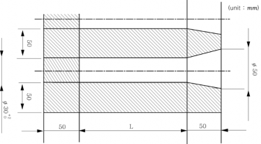
Fig 2.1.13 Sample distance
(5) Cast test samples are not to be stripped from the moulds until the metal temperature is below 500°C.
(6) Integrally cast samples may be used when a casting is more than 20 mm thick and its mass ex-
ceeds 200 Kg, subject to agreement between the manufacturer and the purchaser. The type and location of the sample are to be selected to provide approximately the same cooling conditions as for the casting it represents and also subject to agreement.
(7) The numbers of test specimen are as below
(a) With the exception of (d) below, at least
(b) With the exception of (c) below, a batch
![]()
![]()
See Guidance :
one test sample is to be cast with each batch. consists of the castings poured from a single ladle
of metal, provided that they are all of similar type and dimensions. A batch should not nor-
mally exceed two tonnes of fettled castings and a single casting will constitute a batch is its mass is 2 tonnes or more.
![]()
(c) For continuous melting of the same grade of cast iron in large tonnages the mass of a batch may be increased to the output of 2 hours of pouring.
(d) If one grade of cast iron is melted in large quantities and if production is carefully moni-
tored by systematic checking of the melting process, such as chill testing, chemical analysis or thermal analysis, test samples may be taken at longer intervals.
(8) All test samples are to be suitably marked to identify them with the castings which they
represent.
(9) Where castings are supplied in the heat treated condition, the test samples are to be heat treated together with the castings which they represent. For cast-on-test samples the sample shall not be cut off from the casting until after the heat treatment.
(10) One tensile test specimen is to be prepared from each test sample. Where test samples of oth- er dimensions are specially required the tensile test specimens are to be machined to agreed dimensions.
(11) All tensile tests are to be carried out using test procedures in accordance with the require- ments specified in 203. 1.
7. Test and inspection
(1) All castings are to be cleaned and adequately prepared for examination. The surfaces are not to be hammered, peened or treated in any way which may obscure defects.
(2) For grey iron castings, testing and inspection may not require the presence of the Society's sur-
veyors, except where specially specified in connection with the design.
(3) For the steel propeller castings and spheroidal iron castings, testing and inspection may require the presence of the Society"s surveyor.
(4) When required by the relevant construction Rules, castings are to be pressure tested before final acceptance.
(5) Unless otherwise agreed, the verification of dimensions is the responsibility of the manufacturer.
(6) Supplementary examination of castings by suitable nondestructive testing procedures is generally not required except in circumstances where there is reason to suspect the soundness of the casting.
8. Rectification of defective casting
(1) At the discretion of the Surveyor, small surface blemishes may be removed by local grinding.
(2) Subject to the prior approval of the Surveyor, castings containing local porosity may be rectified by impregnation with a suitable plastic filler, provided that the extent of the porosity is such that it does not adversely affect the strength of the casting.
(3) Repairs by welding are generally not permitted.
9. Retest procedure Where the tensile test fails to meet the requirements, additional test may be carried out in accordance with the requirements of 109.
10.Marking Grey iron castings which have satisfactorily complied with the required tests are to be marked with the identification mark in accordance with the requirements in 110.
507. Spheroidal or nodular graphite iron castings
1. Application
(1) These requirements are to apply to the Spheroidal or nodular graphite iron castings (hereinafter referred to as "iron castings") intended to be used for propeller or important parts of machinery.
(2) These requirements are applicable only to castings where the design and acceptance tests are re- lated to mechanical properties at ambient temperature. For other applications additional require-
ments may be necessary, especially when the castings are intended for service at low or ele-
![]()
![]()
vated temperatures. See Guidance
(3) Where deemed necessary
Guidance![]()
(4) Where small castings are procedures for testing and
2. Manufacture
(1) The manufacturer has the
![]()
by the Society, KS or equivalent thereto may be applied. See
produced in large quantities, the manufacturer may adopt alternative inspection subject to the approval of the Society.
necessary manufacturing and testing facilities and the manufacturing
processes are to be approved by the Society.
![]()
(2) Suitable
mechanical methods are to be employed for the removal of surplus material from
castings. Thermal cutting processes are not acceptable, except as a preliminary operation to me-
chanical
methods.
(3) Where castings of the same type are regularly produced in quantity, the manufacturer, subject to
the approval of the Society, is to make any tests necessary to prove the quality of the proto- type castings and is also to make periodical examinations to verify the continued efficiency of the manufacturing technique. The Surveyor is to be given the opportunity to witness these tests.
3. Grade and specified in only.
mechanical properties Grade
Table 2.1.79. However, Brinell
and mechanical properties of castings are to be as hardness values are intended for information purposes
![]()
![]()
![]()
![]()
![]()
![]()
Table 2.1.79 Grade and mechanical properties
Specified min. tensile strength (N m m ) | 0.2% proof stress (N m m ) | Elongation (%) | Brinell hardness values | Impact energy | Typical structure of matrix | ||
Test temp.( ) | kV(2) (J) min | ||||||
Ordinary qualities | 370 min. 400 min. 500 min. 600 min. 700 min. 800 min. | 230 min. 250 min. 320 min. 370 min. 420 min. 480 min. | 17 min. 12 min. 7 min. 3 min. 2 min. 2 min. | 120-180 140-200 170-240 190-270 230-300 250-350 | - - - - - - | - - - - - - | Ferrite Ferrite Ferrite/Perlite Ferrite/Perlite Perlite Perlite or Tempered |
Special qualities | 350 min. 400 min. | 220 min. 250 min. | 22 min.(3) 18 min.(3) | 110-170 140-200 | +20 +20 | 17(14) 14(11) | Ferrite Ferrite |
NOTE 1. For intermediate values of specified minimum tensile strength, the minimum values for 0,2 % proof and elongation may be obtained by interpolation. 2. The average value measured on 3 Charpy V-notch specimens. One result may be below the average value but not less than the minimum shown in brackets. 3. In the case of integrally cast samples, the elongation may be 2 percentage points less. | |||||||
4. Chemical composition
(1) The chemical composition of the iron used is left to the discretion of the manufacturer, who is to ensure that it is suitable to obtain the mechanical properties specified for the castings.
(2) When required by the Societies the chemical composition of ladle samples is to be reported.
5. Heat treatment
(1) Except as required by (2) castings may be supplied in either the as cast or heat treated condition.
(2) For some applications, such as high temperature service or where dimensional portant, castings may require to be given a suitable tempering or stress relieving
(3) Heat treatment is to be carried out after any refining heat treatment and before
stability is im-
heat treatment machining. The
![]()
![]()
![]()
![]()
special qualities with 350 N m m and 400 N m m nominal tensile strength and impact test shall undergo a ferritizing heat treatment.
(4) Where it is proposed to locally harden the surfaces of a spheroidal iron castings full details of the proposed procedure and specification are to be submitted for approval by the Society.
6. Selection of test samples and specimens
(1) Test material sufficient for the required tests and for possible re-tests is to be provided for each casting or batch of castings.
(2) The test samples are generally to be one of the standard types detailed in Figs 2.1.14, 2.1.15
and 2.1.16 with a thickness of
2.1.14 or 2.1.16 may, however,
![]()
25 mm. Test samples of other dimensions, as detailed in Figs be specially required for some components.
![]()
(3) At least one test sample is to be provided for each casting and unless otherwise required may be either gated to the casting or separately cast. Alternatively test material of other suitable di- mensions may be provided integral with the casting.
(4) Where separately cast test samples are used, they are to be cast in moulds made from the same type of material as used for the castings and are to be taken towards the end of pouring of the
castings.
(5) The samples are not to be stripped from the moulds until the temperature is below 500°C.
(6) For large castings where more than one ladle of treated metal is used, additional test samples
are to be provided so as to be representative of each ladle used.
(7) As an alternative to (3) above, a batch testing procedure may be adopted for castings with a fettled mass of 1 tonne or less. All castings in a batch are to be of similar type and di-
mensions, cast from the same ladle of treated metal. One separately cast test sample is to be provided for each multiple of 2,0 tonnes of fettled castings in the batch.
(8) All test samples are to be suitably marked to identify them with the castings which they
represent.
(9) Where castings are supplied in the heat treated condition, the test samples are to be heat treated together with the castings which they represent.
(10) One tensile test specimen is to be prepared from each test sample.
(11) All tensile tests are to be carried out using test procedures in accordance with the require- ments specified in 203. 1. Unless otherwise agreed all tests are to be carried out in the pres- ence of the Surveyors.
(12) Impact tests may additionally be required and in such cases a set of three test specimens of agreed type is to be prepared from each sample. Where Charpy V-notch test specimens are
used, the dimensions and testing specified in 202. 3 and 203. 2.
procedures are to be in accordance with the requirements
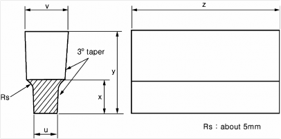
Standard sample | Alternative sample when specially required | |||
Case 1 | Case 2 | Case 3 | ||
u(mm) | 25 | 12 | 50 | 75 |
v(mm) | 55 | 41 | 90 | 125 |
x(mm) | 40 | 30 | 60 | 65 |
y(mm) | 100 | 80 | 150 | 165 |
z | To suit testing machine | |||
![]()
Fig 2.1.14 U-type test sample
![]()
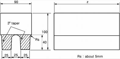
Fig 2.1.15 Double U-type test sample
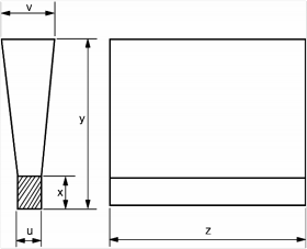
Standard sample | Alternative sample when specially required | |||
Case 1 | Case 2 | Case 3 | ||
u(mm) | 25 | 12 | 50 | 75 |
v(mm) | 55 | 40 | 100 | 125 |
x(mm) | 40 | 25 | 50 | 65 |
y(mm) | 140 | 135 | 150 | 175 |
z | To suit testing machine | |||
Fig 2.1.16 Y-type test sample
7. Test and inspection
(1) All castings are to be cleaned and adequately prepared for examination. The surfaces are not to be hammered, peened or treated in any way which may obscure defects.
(2) Before acceptance, all castings are to be visually examined including, where applicable, the ex-
amination of internal surfaces. Unless otherwise agreed the verification of dimensions is the re- sponsibility of the manufacturer.
(3) When required by the relevant construction Rules, castings are to be pressure tested before final
acceptance.
(4) Supplementary examination of castings by suitable nondestructive testing procedures is generally
not required except in circumstances casting. However, cast crankshaft are
like indications are not allowed.
where there is reason to suspect the soundness of the
to be subjected to a magnetic particle inspection. Crack
![]()
(5) For crankshafts the metallographic examination is to be carried out as followings;
(a) When required, a representative sample from each ladle of treated metal is to be prepared for metallographic examination. These samples may conveniently be taken from the tensile test specimens but alternative arrangements for the provision of the samples may be adopted
provided that they are taken from the ladle towards the end of the casting period.
(b) Examination of the samples is to show that at least 90 % of the graphite is in a dispersed
spheroidal or nodular form. Details of typical matrix structures are given in Table 2.1.79
and are intended for information purposes only.
8. Rectification of defective casting
(1) At the discretion of the Surveyor, small surface blemishes may be removed by local grinding.
(2) Subject to the prior approval of the Surveyor, castings containing local porosity may be rectified by impregnation with a suitable plastic filler, provided that the extent of the porosity is such that it does not adversely affect the strength of the casting.
(3) Repairs by welding are generally not permitted.
9. Retest procedure Where the tensile test fails to meet the requirements, additional test may be carried out in accordance with the requirements of 109.
10. Marking Spheroidal iron castings which have satisfactorily complied with the required
tests are
to be marked with the identification mark in accordance with the requirements in
110.
![]()